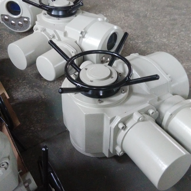
Product
Type Specification and Main Performance Parameters of Z15 Valve Electric Device
Model Specification
Nominal Torque (N.m)
Nominal thrust (KN)
Maximum stem diameter (mm)
Maximum number of turns (circles)
Manual
speed ratio
Output Speed (r/min)
Motor Power (KW)
Reference Weight (Kg)
Z5
Fifty
Twenty
Twenty-eight
Sixty
1:1
Twelve
Zero point one two
Twenty-eight
Z10
One hundred
Forty
Twenty-eight
Sixty
1:1
24/36
0.25/0.37
Forty-five
Z15
One hundred and fifty
24/36
0.37/0.55
Fifty
Z20
Two hundred
One hundred
Forty
Sixty
1:1
18/24
0.37/0.55
Fifty-five
Z30
Three hundred
18/24
0.55/0.75
Fifty-eight
Z45
Four hundred and fifty
One hundred and fifty
Forty-eight
One hundred and twenty
1:1
(20:1)
24/36
1.1/1.5
One hundred and ten
Z60
Six hundred
24/36
1.5/2.2
One hundred and twenty
Z90
Nine hundred
Two hundred
Sixty
One hundred and twenty
1:1
(25:1)
24/36
2.2/3
One hundred and thirty-nine
Z120
One thousand and two hundred
24/36
3/4
One hundred and forty-two
Z180
One thousand and eight hundred
Three hundred and twenty-five
Seventy
One hundred and fifty
22.5:1
18/24
4/5.5
Two hundred and fifty
Z250
Two thousand and five hundred
18/24
5.5/7.5
Two hundred and fifty-five
Z350
Three thousand and five hundred
Seven hundred
Eighty
One hundred and fifty
20:1
18/24
7.5/10
Three hundred and thirty
Z500
Five thousand
18/24
10/15
Three hundred and fifty
Note 1: Other rotational speeds can be provided according to user's requirements: 12/18/24/30/36/42/48/60 (r/min)
Note 2: When the product provides a four-layer counter, the maximum number of turns is Table 1 *10
II. Installation, disassembly and precautions of Z15 valve electric device
The installation form of this electric device has no principle requirement, but the motor is in the horizontal state and the cover of the electric box is in the horizontal or vertical upward state. This is the recommended installation form, which is conducive to lubrication, debugging, maintenance and manual operation.
2. The space required for the maintenance inspectors to disassemble the components should be guaranteed during installation.
3. The axial clearance between the teeth connected with the valve is not less than 1~2 mm.
The bolts connected with the valve shall not be less than 8.8 grade.
When used in open stem valves, check whether the stem extension is consistent with the length of stem sheath.
When disassembly is required, the manual wheel should be rotated several times before the valve is slightly opened.
7. When installing, disassembling and debugging, the sealing surface, sealing parts and explosion-proof surface of explosion-proof electrical installation shall not be damaged, and the rust-proof oil shall be coated on the explosion-proof surface, and the cover of the electrical cover shall be tightly sealed to prevent rainwater or moisture from entering.
Windows should not collide with hard objects.
9. The electric device is of short-term working system. The continuous working time shall not exceed the nameplate calibration time.
When valve is not used frequently, it should be checked regularly, maintained and operated. It is recommended that the valve should be operated at least once a month for no more than 10 minutes.
