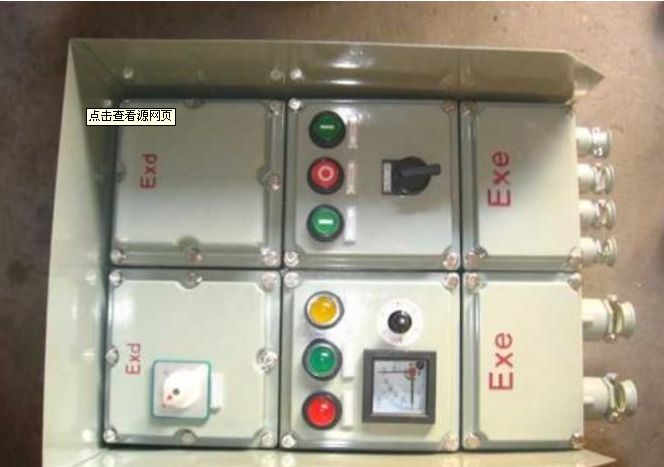
Product
Basic Description of Electric Valve Explosion-proof Control Box
Electric valve control box is one control, two control, three control box, one control, two control box. DKX electric valve control box is an electric control box matched with the electric device produced by our company.
Power supply: conventional, three-phase 380V (50Hz) three-phase four-wire system; special, 220V (50Hz) single-phase system
Ambient temperature: -20-60 C
Relative humidity: <80% (at 25 ~C). Flameproof type < 95%
Type of protection: General type, outdoor type for non-flammable, explosive and non-corrosive media sites. The flameproof flameproof mark is d II BT4, which is used in factories. It is suitable for the protection grade of sexual gas mixtures with class II A and class II B in environment: the flameproof flameproof grade is IP55.
Working Principle of Electric Valve Explosion-proof Control Box
The circuit of the control box is mainly composed of four parts: the control circuit, the working display circuit, the opening indicator circuit and the main circuit (the stroke and moment micro-switch KXK, GXK, KZK, GZK and the motor in the valve electric device). When the power of the control box is connected, the power indicator lights up, the field/remote control indicator lights green, and the control box is in the remote control state. When the valve is in the "full open" position, the green indicator on the panel is on, the yellow indicator on the "full close" position is on, and neither indicator is on when the valve is between the "full open" position and the "full close" position. The "field/remote control" button is the field/remote control selection key, which is released into the remote control status indicator to show green. Press to show the red light for the on-site status indicator. When the control box is selected as the remote control state, the buttons such as "open valve", "close valve" and "stop" on the panel of the control box play a controlling role. The "on-site" and "off-site" buttons on the field electric devices do not work (when the users choose the electric devices, the on-site control buttons are optional, so some users'electric devices may not have the on-site control function, but the absence of the on-site control function does not affect the remote control function of the control box. When choosing the control box as the on-site state, the buttons of "on-site opening" and "off-site" on the electric device play a controlling role, while the buttons of "on-site opening", "off-site closing" and "stop" on the panel of the control box do not work. Press the "open valve" button, the power supply of the motor is connected, the motor rotates. When the valve reaches the "full open" position, the 1GXK micro-switch is touched by the cam, and the motor stops turning. At the same time, the 2GXK micro-switch is touched by another cam, indicating that the yellow indicator light of the "valve switch" is on. When the electric valve needs to stop in the course of opening or closing, the "stop" button can be pressed. In the process of opening or closing the electric valve, if there is an "over-torque" situation, the cam of the electric device will touch one of the two micro-switches KZK or GZK. The motor will stop turning and turn on the alarm circuit. The red fault indicator light on the panel is on, and the buzzer will emit a 4 KHz alarm sound.
Installation and Use of Electric Valve Explosion-proof Control Box
First of all, according to the instructions for the use of electric devices, do the debugging preparation before power-on, and then according to the electrical schematic diagram of the control box and the wiring diagram of electric devices, after checking correctly, turn on the power supply.
At this time, if the red RD and green GN are on, indicating that the electric valve is in the middle position, after checking the correct motor phase sequence, the operation opens to the SO according to Niu, the electric device in place should stop working, when the red RD is on, the green GN is off, indicating that the valve is in the full open position; when the operation closes to press Niu SC, the electric device should stop working when it is in place. At this time, the red light RD is off and the green light GN is on, indicating that the valve is in the fully closed position. In the process of opening, the red light RD flashes, and the green light GN is always on; in the process of closing, the green light GN flashes and the red light RD is always on.
Debugging of opening indicator: Adjust the potentiometer W1 on the opening indicator in the electric device and the potentiometer W2 in the control box to make the opening meter indicate 0 when the electric valve is in full-closed position and full-closed position.
